Last time I showed a Hewlett-Packard 3465A multimeter that I bought pretty cheap. It was described as powering up but misbehaving and I got it for one reason – to do science to it.
For some time now I wanted to build my own “multimeter”, though that’s a bit of a stretch as far as the name goes – it would probably only do DC voltages but maybe also resistance if I could come up with a good enough current source. Autoranging because actually it’s easier these days to have an MCU or some logic drive a couple of relays than to design/find a complicated gang switch. And if I could get my hands on suitable precision shunts then DC current measurements would also be possible. I did not exactly expect to build a quality instrument, no, rather it was supposed to be a learning exercise.
Now, one could just get an ICL7106 and build a 3.5 digit meter out of that and a few extra parts (like the 7-segment displays) but that’s not how I roll. I wanted to make my own dual slope A/D converter, with (MOS)FET switches, voltage reference and all the control logic including auto-zero, averaging and digital calibration – the whole works. Eventually though I figured that maybe trying to fix a broken meter rather than building one would be a better idea considering my goals and lack of experience.
The HP multimeter was promising but ultimately a failure – in the sense that all I did was take it apart, remove the dead NiCd cells, clean it, flood the switches with contact cleaner, put it back together and it worked. So well in fact that I was impressed and decided not to tinker with it. It’s a really good device – I actually ended up using it quite a lot.
So, back to square one, I got me another cheap multimeter – a Fluke 8600A. I’m not very fond of Flukes even if some people consider them to be the superior brand. Obviously this is 40+ year old tech and times (and quality) have changed but comparing the guts and performance of both HP and Fluke I have to say the HP wins, hands down. Here’s the seller’s photo:

and a link to EEVblog forums post that will show you how the Fluke should look inside.
Well, mine has a few issues here and there:

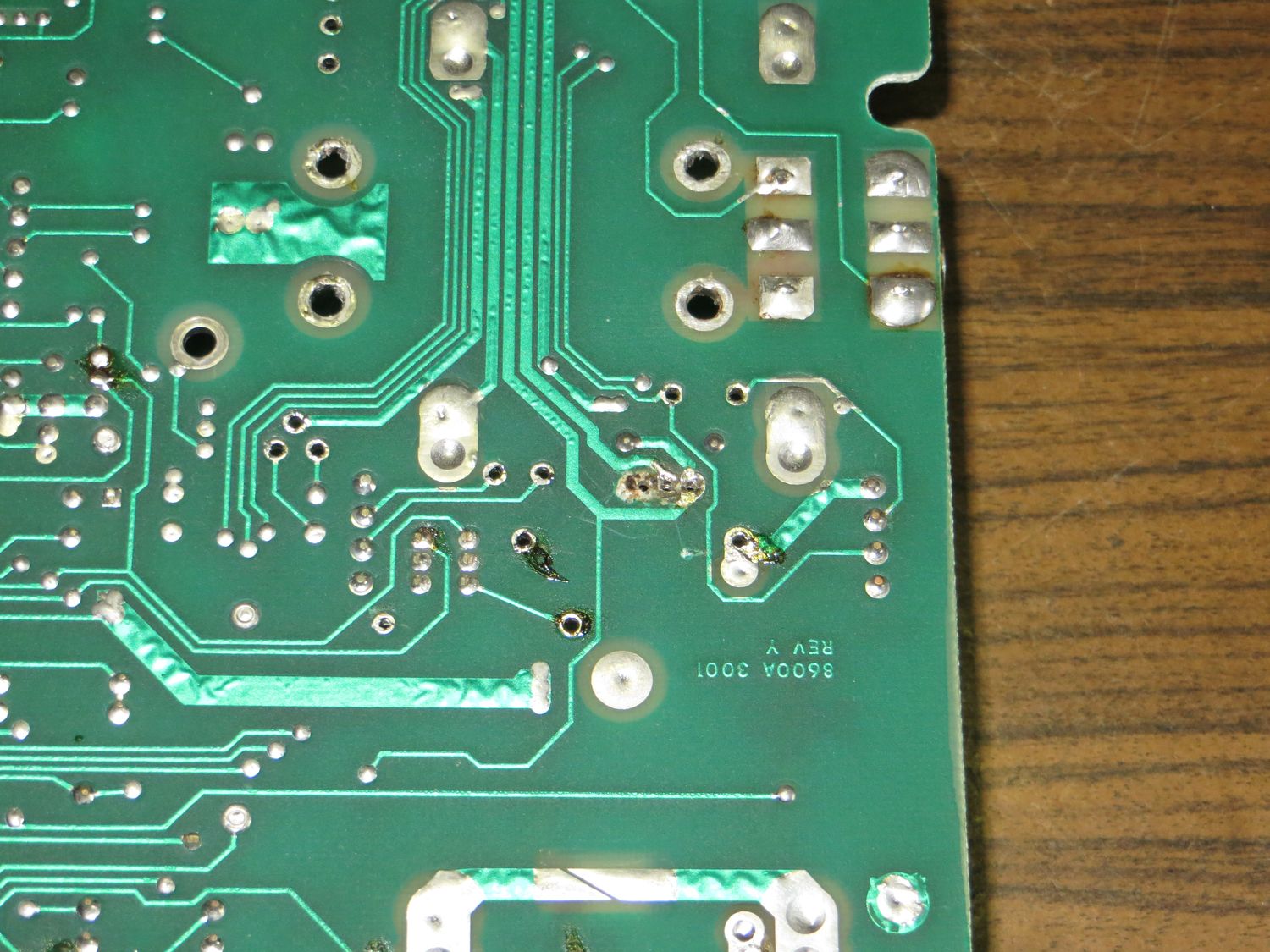
Power filtering electrolytic capacitors are gone. So is the 5V rail regulator along with its heatsink. Also, and that’s the major pain in the butt, so is the transformer – all missing. Worse yet, whoever removed the voltage regulator was not very proficient with the soldering iron:

Turns out the very pin that connects the regulator to GND is also the common ground tie point between digital and analog sections of the meter. So with the via all but destroyed I had pretty high impedance between DGND and AGND and it took me quite a while before I found on the schematic these two should be in fact connected.
Well, I can supply the power (+5V, +15V and -15V) from external PSU for now. But what’s this, the metal shield around AC to DC converter is missing as well. Also, I see some burn marks:


Not exactly sure how it happened but the precision wirewound resistor in the ohms converter burned up, and somebody replaced it with what seems to be a metal film 1% resistor. But I have to say they did a pretty good job because originally it was a 9.95K 5W 0.1% – good luck finding something like that. The replacement is 9.96K which is good enough except maybe temperature coefficient but not much can be done about that. Same for the PCBs but at least the carbonized material around the leads has been removed. Here’s what the add-on cards look like up close:


The voltage divider on the photos is already missing the 50 ohms calibration pot, I removed it because it was open. Possibly went kaput in the same event as the ohms converter? Didn’t have a spare on hand so for now I just put in 2 resistors just to be able to continue testing. You probably noticed the missing markings on one of the reed relay coils, somebody was messing with that one too.

Meter had problems with autoranging so the first thing I suspected was the small ROM that’s used to drive relays – it’s known to die. That turned out to be mostly good, one bit was glitched in the 200mV AC range. Some people claim this part is actually a bipolar PROM, not mask-ROM, which would make the zero-bit recoverable with a suitable programmer (unlike modern EPROMs, bipolars have all zeros by default and are programmed to ones by burning connections inside the chip). That was however moot point as I don’t have such programmer, and shortly after one of the outputs died – could be I killed it by shorting with probe tip at some point.

That’s the ROM testing setup, since it has only 32 addresses I can just test all of the values in 10 minutes by switching the inputs with wires. The output that died is that single LED on top, the photo and notes I made prove it was working up to a point.
The fuses were missing (both the line power and the current measurement protection), and the whole thing would pretty much always show overload no matter what mode or range was selected. This was eventually traced to busted FETs switching input and zero to the A/D. In general I had to:
- rebuild the power supply
- find and replace faulty logic chips
- fix issues with A/D converter
- clean input jacks area and redo wiring
- fix broken AC to DC converter
- replace burned PCBs (and dying reed relays in the process)
- recalibrate everything (which required replacing a selected resistor)
I’m going to get into the details of all this eventually, for now though I’d like to present my idea of replacing the faulty ROM. I’ve seen people use a more modern EPROMs like 2764 (which is also obsolete now but at least obtainable and mostly supported), but that is 28-pin wide body part. The only way you can fit that in is on wires, that’s ugly.
With some minimal pin swapping I’ve managed to use GAL16V8 instead because the contents of the ROM is simple enough that it can be turned into logic equations that fit on the part. And the GAL is small enough that it actually will fit into the original socket:


The results were promising but two issues came up. First one was some weird latching in invalid state when switching away from DC current mode that caused the GAL to basically short-circuit the 5V line. Good thing I had this running from external PSU with current limits. This particular problem was easily solved by adding a 10uF ceramic SMD capacitor right on the chip, as close to power supply pins as possible. I have to say Fluke apparently did not belive in any logic chip power filtering, there’s basically nothing of the sort on the whole PCB and the 2-layer layout means pretty long traces. So long in fact that the usual 100nF wasn’t cutting it, 1uF almost fixed it completly, so I picked 10uF to be on the safe side. That and the whole issue with MLCC caps derating under DC bias.
Second problem was also DC current mode related – the way Fluke implemented it was by cutting power to the ROM and all the relays while it was selected. This is because current measurement is still manually ranged on these early models, by selecting the correct shunt resistor, and the A/D is permamently set to 200mV range to keep the burden voltage low. Now this power cutoff worked fine with ROM becuase it has open-collector outputs that in turn drive PNP transistors (that in turn drive the relay coils). For that to function properly the transistors have pull-ups to 5V that shut them off when ROM is not driving the base low. GAL however is a modern part with push-pull CMOS outputs protected by diodes to VCC and GND. So those resistors would backfeed 5V to the GAL, via those diodes, providing it with enough power to actually function and drive some of the transistors when it shouldn’t. So I had to add a mod, a small NPN transistor that would isolate the GAL from GND when the power was cut. This has a minor downside of shifting the GAL ground up by some 0.2V in the on state, but that’s not an issue in this circuit. See if you can spot the tiny SMD part (note no external base or bias resistors, these are built into the transistor package):

This solution works very well and is almost a drop-in replacement, except for that small mod. It’s not a big deal though as it will also work properly with the original ROM in the socket – which was one of my goals (in case I’ve managed to revive the ROM somehow).
BTW, the reason I got that Fluke and not something else in the first place was this add-on card:

This is opto-isolated digital output board that sits over the main PCB, I have plans to try and build an interface between it and a Raspberry Pi, which would allow me to turn this experiment into a networked logger. A dumb one since this board only provides output and can’t affect the meter operating mode or range, but that is still pretty useful to me.