DocBrowns are finally here, orders will open this Saturday (2022-05-14) at 20:00 CEST. While sending confirmation emails for Rheas I’ve noticed that my email provider is again being blocked/bullied by some sites, no doubt to force me to switch to more “reliable” service. At least this time I got notified of the block, and the offenders are hanmail.net and bellsouth.net. Keep that in mind if you use those because I ask for Marty serial numbers and if I’m blocked you will not be able to see and answer my request.
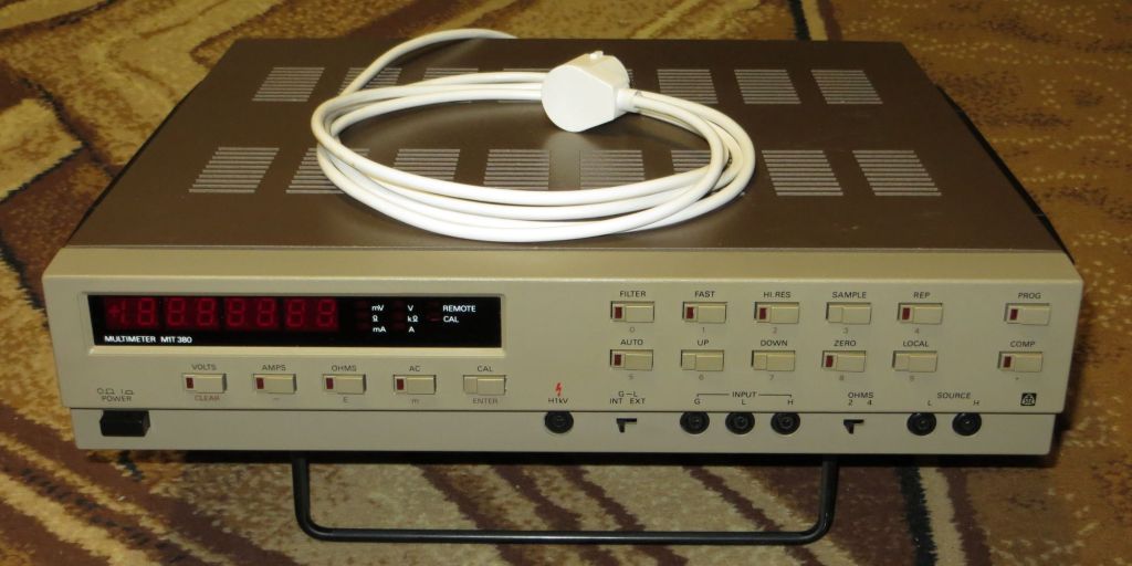
And now time for some random photos. I got a new (well, new to me) toy for some 50 EUR shipped:

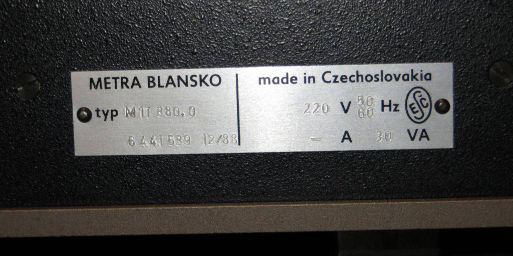
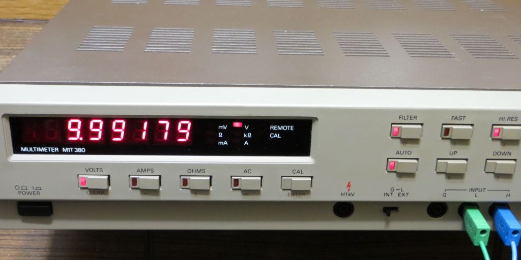
It’s an M1T 380 multimeter from Metra. In theory it offers 6 and 1/2 digits in VOLTS/AMPS when using rather slow (~2s) HI.RES mode, in reality I might have to mod it to provide better temperature stability (noise doesn’t seem to be a problem, not as far as I can tell – I’d need a modern and calibrated meter of this class to compare with), but the good news is some people already tried that with good results.

This is a 380.0 model, meaning no external interfaces, something I intend to change. I’d like to have a modern USB, or at least RS232 port (especially since it would offer full control over the instrument). I have a manual and full schematics – it’s all in Czech (which I don’t speak, not to mention all the technical terms) but I get enough of it not to be completly lost.
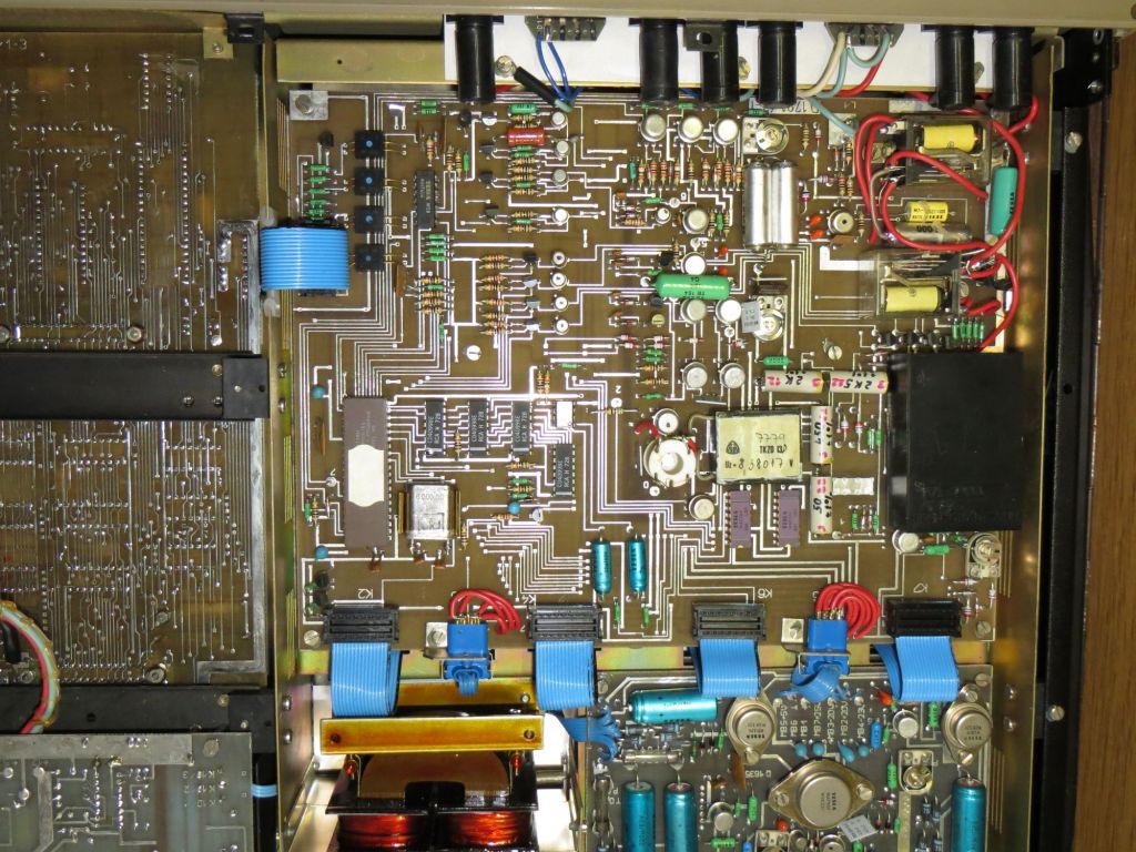
Seems to be in working order, after some cleaning and fuse replacement. One of the tantalum capacitors died and shorted after a few power-ups, that can happen with the old “teardrop” types. It was a bit annoying the cap in question was a part of the input chopper amp module, it’s a separate black box (no, really, see photos below) on A/D converter board that I had to desolder to even get inside. I’ve seen this entire box being replaced with a single modern OpAmp, might just do that too eventually.


The ROM is 8KiB (4x 2716 EPROM) and pretty much full. I’ve built a cable to interface with this board and dump the ROM (and calibration data), I’m slowly progressing through the disassembly. I opted to use Z80 mnemonics since I don’t really speak original Intel 8080. And the code, to fit into this space, has some hacks in it, and some bugs too, which doesn’t make it any easier.
The idea is to add the external interface board based on original schematics of that add-on module. There is a dump of the 2KiB external ROM of extra 8080 code for the RS232 board but I’m not sure it will work properly with my FW. I’ve compared it to the v3.6 which is known to work and there some patches in places where the REMOTE function takes over, so that might be a clue I need a FW update first. And removing these 2716 chips is not something I’m looking forward to, these PCBs are extremly fragile. Super easy to rip vias or traces.
So perhaps I should create my own CPU board instead with the RS232 interface already on it, I could fit all of it by using Z80 in place of 8080 (with a few tweaks to the timing-critical code) and modern RAM/EEPROM (or Flash, or even just EPROM) chips. This also saves me from having to work around another Czech-specific socket/plug combo that is unobtainium (that green one near PCB edge) and have just one PCB and some wires to the plug on the back of the unit.
Or, and this is something I’m seriously considering now, do away with Z80, put a modern Cortex-M MCU there. Run either my own code (after I figure out the complete protocol to control A/D board), or the 8080 code in emulator, or a mix of both. I could probably fit all of that in 5V compatible M0 part + MAX232 for the serial port. Or perhaps use M4F with hardware FPU, a few more chips to translate 3V3 to 5V, and code a few more functions like sliding window filter for example.

UPDATE: DocBrown orders are closed. I will process the orders and send out confirmation emails in 1-2 days, though I can already tell there’s a lot. I probably don’t have enough stock at the moment. I will have more but that will take 2 months or so, I’m planning on doing Wizards next and that takes a lot of my time.